|
Race Engine
Development
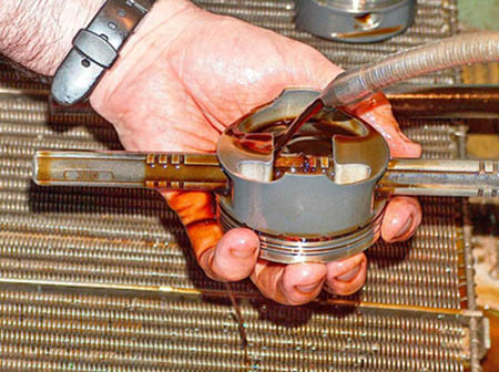
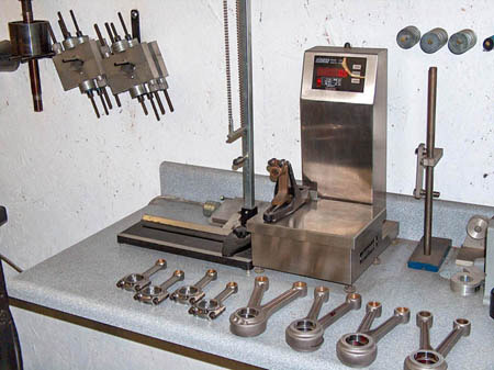
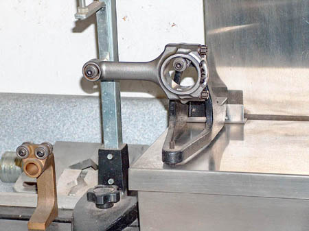
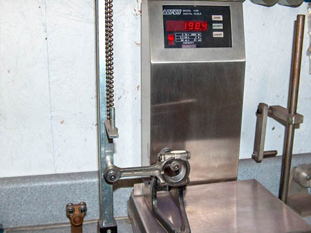
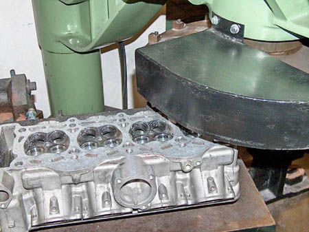
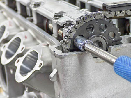
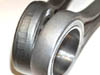
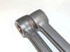
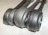
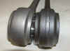
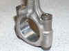
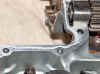
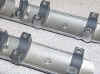
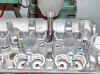
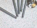
| Here are some pics of
a very small fraction of the type of engine development work we do
here in conjunction with all the engine related products we
innovate, design, and manufacture. These pics are mainly from
the motorcycle race engine department side. We have been careful not
to reveal any of our many secrets learned over the last 28 years of
doing this form of work. Instead we are showing just typical,
first class work. This is just plain old 'grass roots' work, that is
just standard for true professional engine builders and factory race
team engine designers. Unfortunately most shops that do engine
work, don't even truly understand many of the below aspects of
engine building. We have seen so many engines come to us
over the years, that had been built by well know name engine
builders, that are actually very unfortunate samples of their
customers being taken to the cleaners. Not so much by price,
but rather what they got, (or thought they got) for whatever price
they did pay. Sometime we may put up a section of pics of
"disaster waiting to happen" poorly machined, (or not
machined at all) components in engines or some that were
disasters. Since we have done engine annalists for other
companies/racers for many years, we have a lot of very interesting
data, and some very very humorous (except for the engine owner of
course.)
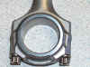
Remember, if you don't have a properly
build strong bottom half of the engine, eventually it doesn't matter
how strong the engine runs, as it won't run too long, if its truly
making real HP!! It's the
"unglamorous" parts, that the true racer/team owner should
be concerned about first!! You'll never win if you don't
finish first!!
|
 |
 |
|
|
 |
 |
 |
 |
 |
 |
 |
 |
 |
 |
 |
 |
 |
 |
 |
 |
 |
 |
 |
 |
 |
 |
 |
 |
|
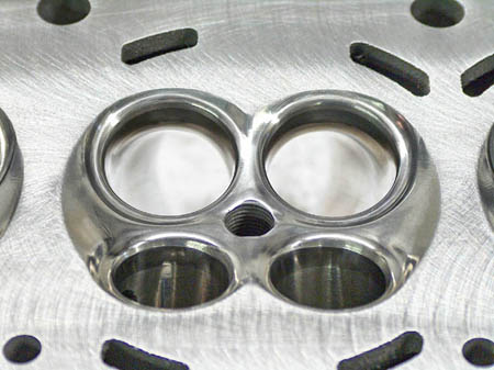
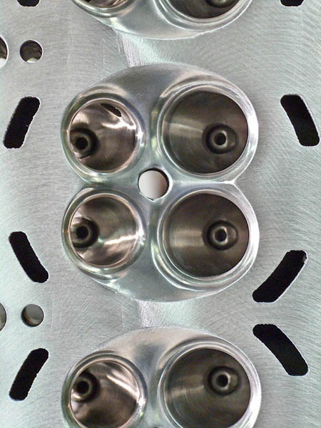
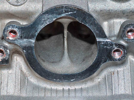
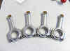
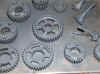
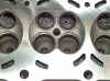
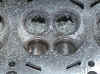
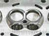
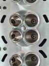
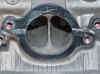
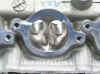
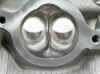
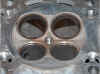
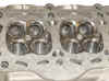
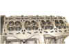
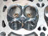
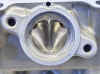
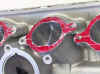
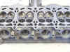
It's common knowledge among
"TRUE" racing professionals that even for a motorcycle
engine, 20, $30,000 or even twice that for certain factory level plus,
engines is not too much to pay. If you're getting what you wanted.
We've just seen too many people pay way too much for engines
not really worth half what they paid for them. As we get time, we'll
add more, just for food for thought. We aren't in the business nor
would we publicly name any of these 'engine builders' as we try to
be a whole lot more professional than that. We'll some time be
posting engine components that show how you don't want your engine
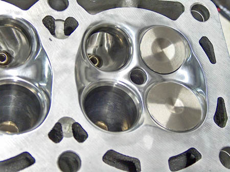
builder to build your engine as well. A
very important note here; The finish appearance
in the of a chamber or port, as shown below means absolutely
nothing when it comes to performance. You can look at work
that looks beautiful but performs worse than stock. You see pics
regularly in magazines of "beautiful work" that really isn't
worth the hassle of removing the parts & sending them to get
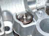
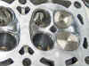
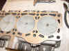
done. Although top level work can look great, its the shaping, contouring,
matching machine work, matching of all related parts, etc etc, that
really matters. Sometimes an area in the head benefits from being as
smooth as glass, sometimes we actually cut grooves in an area, or don't
touch it at all. Sometimes we even weld in an area and rework
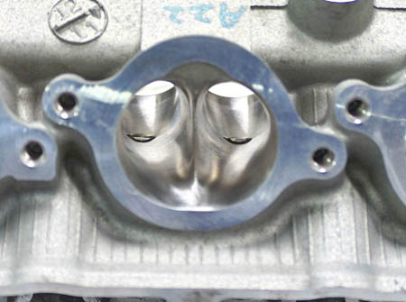
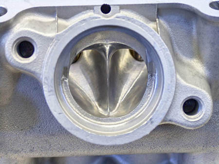
it. The
following pics show just a fraction of what our capabilities are,
but at least will help familiarize some people on some things
they maybe have wondered about for a long time. |
 |
 |
 |
 |
 |
 |
 |
 |
 |
 |
 |
 |
 |
 |
 |
 |
 |
 |
|
|
|
 |
 |
 |
 |
 |
 |
 |
|
|
|
|
|
|
 |
 |
 |
 |
 |
 |
 |
 |
|
|
|
|
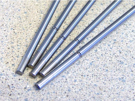
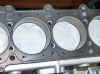
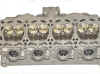
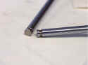
We've
been asked so many times over the years questions about valves &
valve specs, what means what, & what determines what.
Although we could write a good many pages on the subject, here is
just a typical scenario that will answer a few questions. We'll
start with a "Valve Blank", & cover just a few of the
basic but all encompassing issues of making it into a finished
product ready to use. We didn't run the coolant so you could see the
valve better.
|
 |
 |
 |
 |
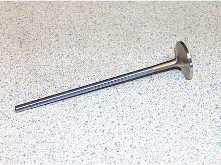
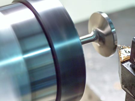
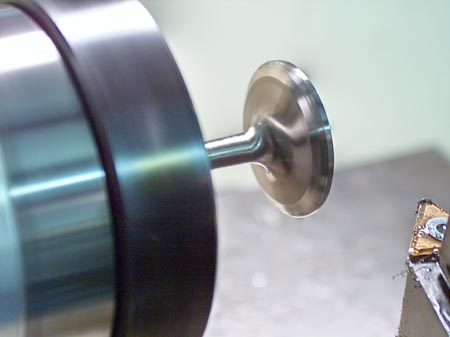
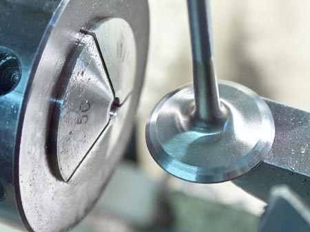
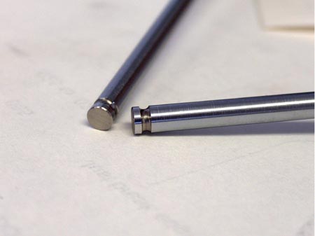
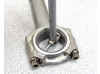
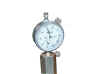
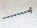
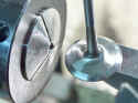
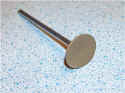
| Here
is a Valve blank. The only things finished are the valve stem dia,
& the valve head back side angle, or tulip profile, sometimes this isn't finished
when acquired. |
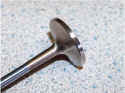
You
can see it has a very thick margin at the moment. |
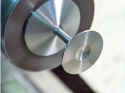
Here
you can clearly see the OD of the valve head being precisely |
Once
the OD is is machined to its exact size, the basic seat angle is
machined, in this case, very close to 45 degrees. |
 |
 |
 |
 |
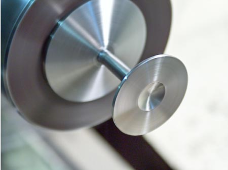
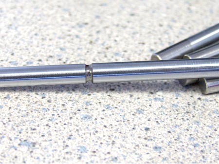
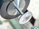
| Before
the seat angle & after. You can see we cut them to a very fine
finish, as you can see the shine & reflection on those surfaces. |
Now
we cut the entire face in till the margin the exact dimension it has
to be. This measurement & the small chamfer on the outer dia of
the valve face are super critical when running close valve to valve clearances
|
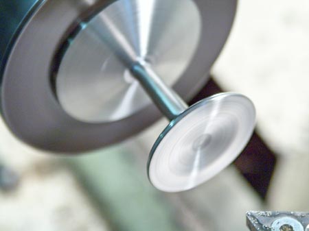
Now
with the margin correct we lighten the valve face, thus the overall
weight of the valve. Its a balance between compression & valve weight
that determines this operation. |
Here
you can see we have cut the back angle which will later be
properly shaped for maximum flow, in accordance to the port throat
design. |
 |
 |
 |
 |
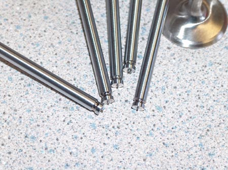
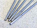
| Once
all of the specs at the head end are all exactly correct for the way
we've designed the geometry we go to the other end. |
You
can see we haven't grooved the top stem yet. This groove is
one of the extremely critical parts of the valve. |
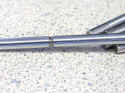
This
groove is not just a groove. There is actually two separate radiuses
along with a straight section as well. This is to ensure the keepers
can lock properly. There are many factors determining ea. aspect
of the groove dimensions. |
The
distance from the top of the groove to the end of the valve is very
critical. It can't be too much or the adjusting shim could come out
of the retainer at the hint of valve float if over- revved. If the
least bit too short, several other problems will occur. |
 |
 |
|
|
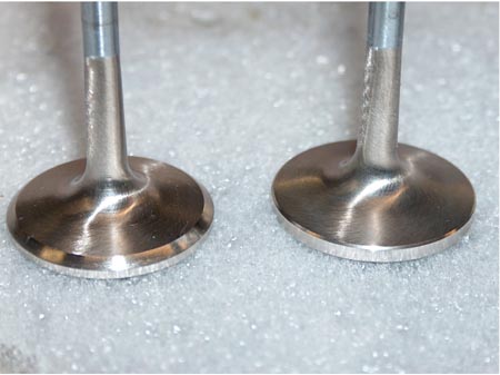
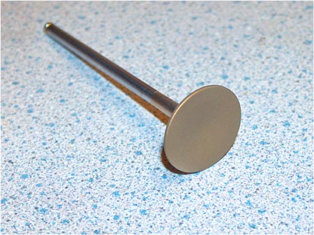
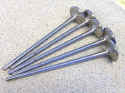
| We
precision grind the tips to the exact spec needed, then put a
critical small precise 45 deg. chamfer around the edge of the tip,
it serves several purposes. |
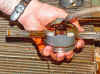
A
finished valve with our Pro-Gold heat barrier applied. |
|
|
| A
general note before reading the valve spec scenario below;
Granted if some
"engine builder" is putting together a typical "race
engine", by their definition, many of the below points don't
matter & unfortunately for his customer, many times don't even
mean anything to the "engine builder". Many
"engine builders" rely on the parts to "just work"
rather than completely understanding & checking ea. aspect of
the components design & how they interact with ea. other. Many don't even check things like valve to
valve clearance. This means one of several things; they are either
unaware of how important that is, they don't care, they don't know
how to ck it, or, they aren't really building a true upper level race
engine. If they were, they would be utilizing all the
"available room possible" to make stout reliable hp &
tq. You
almost always wind up running the intake valve and the exhaust valve
very close to one another (as they pass ea. other) while one is closing & the other is
opening. Using up all the opportunity there is, is one reason for having
cams special ground to our own specs, to maximize inlet & exhaust
flow characteristics.
Some of the factors that determine
all the valve specs are; RPM
you want or need to run, the backside or tulip
profile according to if it's an intake
or exhaust, & what is the bowl
or throat area design. The
depth you want the valve into the
chamber/head, (many times that is determined by how thick the
top of the pistons you are using are,
which then determines how deep you can fly-cut
them). Then the material
you are using for the valves, & if
titanium we use completely different
material for the valve seats
for several reasons. Also cam base circle,
& definitely cam profile,
what springs
you need to run, which is determined by the RPM
you need or want to run, the cam profile, & definitely if its a symmetrical
or non-symmetrical grind which is part of
the cam profile, and then the weight of
the valve. The retainer
style & dimension also goes hand in
hand with valve design. Also, do you want or need to run a undercut
valve stem, for flow or weight, or heat
issues. Are you coating the valve
or not. The type of guide material
you are using for the valve guides is also very critical in
determining the valve specs & visa versa as well. The diameter
of the valve
head. That's a humorous subject in
itself. Many people think that an oversize
valve, in and of itself, allows for more
flow, DEFINITELY NOT SO!! Unless the proper throat work is
done, and in most cases the reshaping of the critical areas in
the combustion chamber are are not properly modified, they can flow LESS
AIR!! and many times cause added unwanted turbulence, & other
problems. But, when many people hear the word oversize valves, they mistakenly
think that that atomically means more power. We see a lot of heads
done by well known & "reputable" facilities,
that quite frankly they should be embarrassed to let out of their building.
But since we are definitely not here to knock anyone in particulars work, we'll
leave it at that!! The
location & angle
you want the valve to be in the head, also determines its
makeup. You can change the angle of the valves, even if its an overhead
cam engine, but that for only the very top dollar Factory plus, level
engines generally. It generally entails oversize
buckets, & installing over-size
OD valve guides, so everything can be
re-machined so the new angles will mate to the cam properly, along
with many more other critical mods.
The above was definitely far from all the
facts concerning engine valves & their configuration, but it gives
the otherwise un knowing person a little idea of just what goes into a properly
built Race Engine. The real critical
fact or point here? We only discussed
one out of a large, vast array of critical engine components
in a Race Engine. Now ponder what
kind of time, knowledge, effort & expense goes into the complete
Engine when finished,!! if its a True Race Engine!!!!!! |
|
|
|
|
 Performance Design Performance Design

136 Airport Road
Headland, Al. 36345
1-334-693-9203
|
|